Warning: This post describes how I modified a commercial power supply, this is dangerous! You have to know what you are doing or you will kill yourself. I’m not responsible for anything you do.
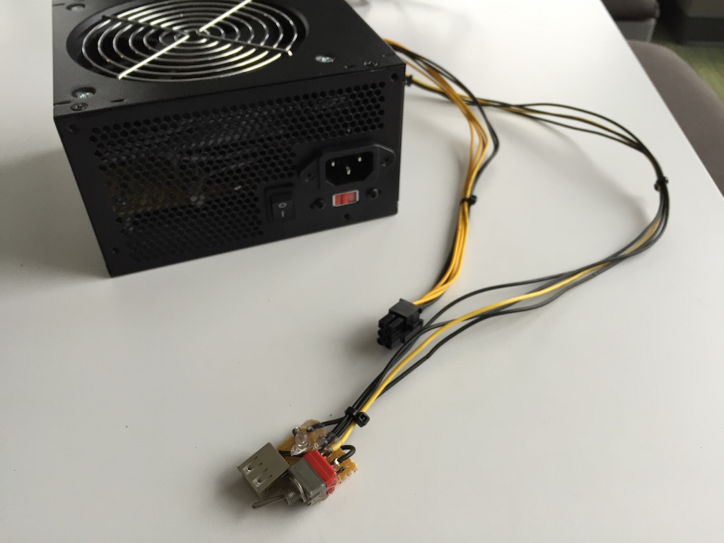
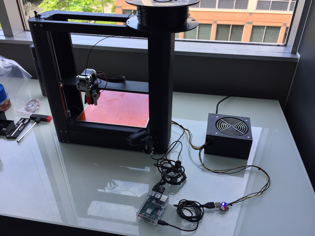
Recently we acquired a printrbot metal plus 3D printer at the CenturyLink Cloud office (we have a small group of makers here). I wanted to add a heated bed but this upgrade requires more current than the default laptop style power supply that was supplied. This problem is solved by using a normal ATX power supply, in fact the heated bed upgrade I purchased came with and adapter that allows you to use the PCI Express plug on the ATX power supply. I wanted to have a cleaner, simpler, solution than having a plain old ATX power supply with a bunch of wires hanging out. Here were my goals/requirements for this project.
Requirements
- Runs quietly, the power supply I bought was extremely loud running at full speed all the time. The printer sits in our team room so this was important.
- A 5v power source to power a RaspberryPI, we use it on conjunction with Octoprint for remote access and control
- Looks, it needs to look good, as I said before it sits in our team room and office tours regularly come look at it.
Parts
- ATX power supply with PCIe Plug
- LED (any color)
- 1/4 W resistor (Ω dependent on your LCD)
- 5W 50Ω resistor
- PCB board
- Switch (optional)
- USB Female Socket PCB mount
- Soldering Iron, screwdrivers, other Misc tools
The Work
-
Because I wanted the fan to run as slowly as possible, maybe not even at all, I wanted to remove any extra wires that I didn’t need. In my case I choose to unsolder all the ATX connectors. In a previous build where I made a bench power supply out of a ATX power supply I simply cut and insulated the wires, but that proved to be just as time consuming. Also the PCB in my power supply had legible silk screening so i didn’t need to keep track of sources and voltages.
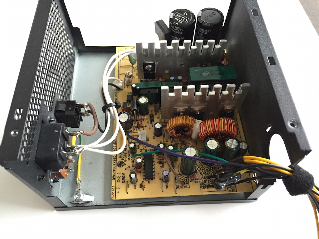
-
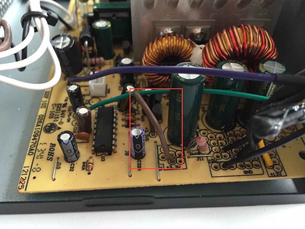
All ATX power supplies have a 3.3v sense line (brown on 24 pin connector) that will automatically shutdown the PSU if 3.3v is not detected. This is used to protect against shorts. Most of the time this line it just spliced in with a 3.3v (orange) wire in the 24 pin connector. This needs to be wire to a 3.3v source. I choose to just cut it short and solder it back to the 3.3v PCB connector. FYI: your power supply may also have a 5v and 12v sense line that you will need to set the voltage on.
-
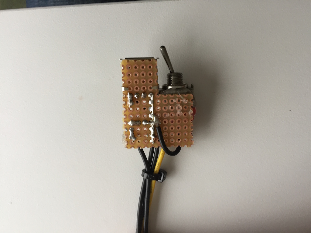
On ATX power supplies you must ground the
PS_ONor green wire on the 24 pin connector to get the unit to turn on. This is basically what pressing the button on the front of your computer does. You can either choose to just ground the wire and solder it in place or for me I installed a switch that would allow me to turn the unit on and off. Because I wanted to be able to turn it on and off I also want to have a nice indicator LED. I probably could have found a more elegant way to do this but because there is lots of 3.3v sources in an ATX supply I wired the 1/4w resistor and LED in line with a 3.3v source and used the same ground as the switch so it would light up when the power supply was on.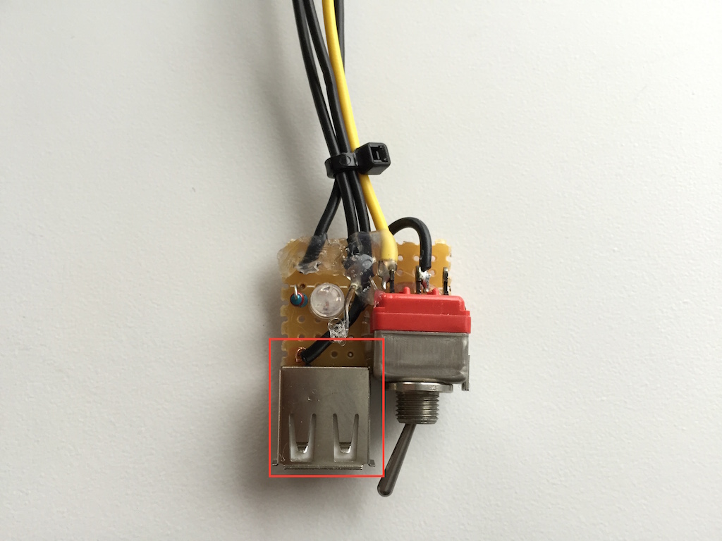
-
I wanted to be able to have a power source for the RaspberryPI we were using to run Octoprint. On most ATX power supplies there is a 5v standby line that is always on even in the
PS_ONline is not grounded. This is why you can sometimes charge devices via USB even if the computer is off. I decided to wire the 5v standby line to a female USB plug and use that to power the PI. This meant that the PI would stay on even if I switch the printer off. I wanted this because I didn’t want to have to deal with gracefully shutting down the PI. Maybe one day I’ll come back and wire in a nice circuit that when switched off turns the PI off gracefully then the power supply.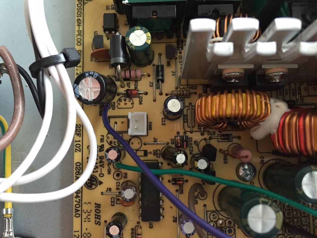
-
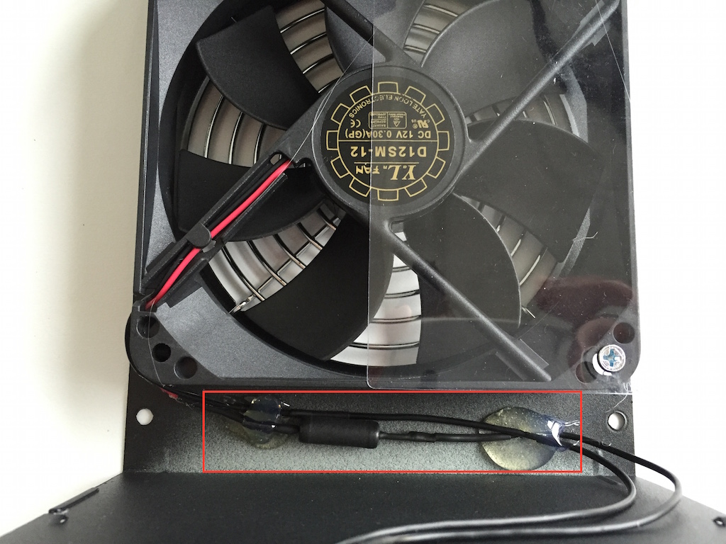
Last but not least I wanted to slow the fan down because on this cheap power supply there was no temperature speed controller and it just ran full blast all the time. The easiest way to do this is to reduce the 12v supply that the fan gets to a 5v supply. This is a fairly common practice and there are tons of tutorials on how to do this and how to get the math right. For me I had a 5W 50Ω resistor and while 5W was overkill and 50Ω didn’t take it to 5v exactly it was close enough for what I was doing. I wired the resistor in line and then hot glued it to a space in the case just so it would stay out of the way.
Done & Working
So there you go a nice clean and simple custom power supply for a printrbot 3D printer. Like I said this is dangerous and you could really hurt yourself. So don’t do this unless you know what you are doing.